



Hardwire Installation of a Two Channel Viofo DashCam - Model A229 Ultra (1 Viewer)

RetiredSteelWorker

Active member
Joined
May 30, 2025
Messages
216
Media
44
Reaction score
129
Location
Mid Atlantic US
I picked up a Viofo dashcam, Model A229 Ultra, when a sale was going off in late July, and just recently got around to installing it in my 25 Lux. This is the 2nd Viofo DashCam I own, and the first install in my GX.

I did a hardwired installation with a front and rear camera, using fuse taps in the interior fuse panel. I did hardwiring to enable parking mode. The installation was an effort spread across a few days, mostly because I figured out the cable routings as I proceeded … figure it out as you go.

If I had to do it over again it would take about two hours, because now I know what fuse locations to use, what trim panels to remove and more importantly how to remove them, where to locate the voltage selector shutoff switch (glovebox), all those details that take time at first. The learning curve.

My overall approach was 1) I wanted all cables hidden, and 2) locate cable runs on the floor not on the roof to be away from overhead air bags, 3) feed the rear camera cable through the weatherproof flexible grommet for a clean look.

Helpful Aids:
Multiple great tips in this ChrisFix Dash Cam installation video, , silicon lubrication for a tight fit in weatherproof grommet, clean cut and sand on a trim piece, etc.

Good overview on removing interior trim panels: Remove ANY vehicle interior trim with THESE tips & tricks - YouTube. Note how this guy effortlessly pops off interior panels.

I have access to Auto Repair Source maintenance manuals, thread, and I referred to them when it was not obvious how to remove a specific trim panel, which was the case for over half of the panels. The helpfulness of the manuals was with diagrams showing where, in what direction and what order to pull or push (manually, by hand). And when a trim tool is needed, which was only for one or two panels.
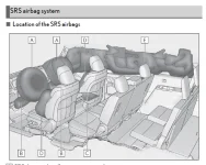
 
Cable runs and Air Bag locations
This image from the Owner’s Manual shows the location of air bags. I did cable runs to avoid these airbags as much as possible. The RH A Pillar from the top of the dashboard up to the headliner is the only location where an air bag is near any of the cables I installed.
1791651497437.webp

Fuse Taps for power from the Interior Fuse Box
I’d like to say pushing fuse taps into slots on the interior fuse box was easy. That was not so for me for two reasons: The fuse box is very, very small, and the fuse box is oriented such that you access it looking up, e.g., rest your head on the floor mat and look up. I couldn’t twist and contort my body into that orientation, so I used a small inspection mirror to do all the work on the fuse box.

Finding two fuse slots, one for always on power (parking mode) and one powered only when the engine is running was very easy. A simple voltmeter and the inspection mirror worked.

For always on power I used the fuse for the right rear door, I stayed away from Hazards, ECUs, Wipers, etc. I wasn’t worried as much about some electrical short or malfunction as I was about deenergizing an ECU and having it go through some learning or recalibration process.

For ‘engine on’ power I used the unused fuse slot adjacent to the USB slot (labeled “ USB NO.1” on the fuse panel). These pics show what I used. These pics are taken looking up at the fuse box, the bottom of the pictures are closest to the engine compartment, the top of the pictures are closest to the passenger seat.

1791651554559.webp
1791651561712.webp


If you use fuse taps you need to know they are directional, not to be confused with polarized. If you install in the wrong direction – they can only be inserted in two different orientations – they will still work but the original fuse will be doing the work for both circuits, which defeats the whole purpose, might trip prematurely. In the case of the open slot a fuse tap inserted incorrectly will not work at all because only one side of the fuse slot has metal spades. You also need to have the tapped leg use a lesser amp fuse than the original leg.

I used two Wago inline connectors (“Lever Nuts”) to connect the two power leads off the fuse taps to the voltage selector shut off switch. Wagos are probably not best suited for vehicle use (constant vibrations, etc.), but I may change out this installation and I like the modular aspect to using them.

1791651590981.webp


I placed the voltage cutoff selector switch (a Viofo HK6 kit) in the glove box. Shown on the left in the next picture. The two cables fit snugly through existing clearance space on the panel you remove to get to the cabin air filter. I plan to modify this later and cut a small access notch to make this a clean application.

On the right in the picture is the (very small) cover to the interior fuse box. The fuse taps sit too proud to allow the fuse box cover to go back on. The cover lists the fuse circuits so it’s critical not to lose it, and to have it readily available if needed. I’ll keep mine in the glove box. The blue painter’s tape holds the white plastic fuse extractor tool (the only one you get with the vehicle) I took from one of the engine compartment fuse boxes, also good not to lose this tool.
1791651625121.webp


Finding a good ground, the black wire in this picture, was easy once trim panels were removed:
1791651643427.webp
 
Trim Panel Removal Sequence
I removed interior trim pieces in five groups, in the sequence listed below. I didn’t plan it this way, it’s simply how it worked out.

I started at the fuse box, then went up (ran two cables up) to the DashCam, then finished running the single cable back to the rear camera.

When I started this I wasn’t sure if I could tuck the cables under the edge of panels without removing the panels. That seemed like a shortcut way to do it, routing under trim panels (e.g., removing the trim panel) is the way to go

Weatherstripping and headliner
This write up does not list where weatherstripping needs to be pulled off, it’ll be obvious, and it comes off easily once you pull hard (which is a good thing). Double or triple check when you reinstall weatherstripping, you do not want to find out you allowed a water leak when it’s too late.

For headliner it’ll also be obvious.

Trim Panel names
I tried to use the formal name of the trim panel, so when you see something in all caps like this “DOOR SCUFF PLATE ASSEMBLY RH” the name is from the Auto Repair Source manuals. When you see this (not all caps) ‘Front Scuff Plate’ then I’m using a shade tree mechanic name. If you want to talk about Toyota and Lexus part names correctly, specifically for interior trim panels, you do need to know the correct names.

Most of the trim panels involved in this have dependencies on other panels, they overlap, may be fastened to each other or to parts of the body or frame, i.e., a handle grip bolted to the frame. The sequence listed below is correct and follows the sequence in the Auto Repair Source manuals.

I only had to use a full trim removal tool on one panel and I confirmed this usage in the Auto Repair Source manuals.

The removal sequence I followed is:
  1. Front Scuff Plate (DOOR SCUFF PLATE ASSEMBLY) up A Pillar to the Headliner.
  2. Two trim pieces around the rearview mirror.
  3. From back end of Front Scuff Plate (DOOR SCUFF PLATE ASSEMBLY) to DECK TRIM SIDE PANEL ASSEMBLY.
  4. Back end of DECK TRIM SIDE PANEL ASSEMBLY up to Headliner
  5. Across Headliner to flexible Weatherproof Grommet to “BACK DOOR CENTER GARNISH” panel, which gets you and the cable to the rear camera
Reinstallation is in the reverse order. Note that it’s a good idea to confirm both cameras are working before reinstalling everything.
 
1 of 5 - Front Scuff Plate (DOOR SCUFF PLATE ASSEMBLY) up A Pillar to the Headliner
The Front Scuff Plate (DOOR SCUFF PLATE ASSEMBLY) is the first panel to be removed, and it has a very tight wire connector to the Lexus light.
1791651819136.webp


1791651838502.webp


The trim piece not shown in the next pic, formal name INSTRUMENT SIDE PANEL RH, is the only one where I needed to use a trim tool, as confirmed in the Auto Repair Source manuals.
1791651864341.webp


The blue trim tool in the upper left in this pic is what I used:
1791651881946.webp


In the next image the free hand orange line parallels the two cables I installed along the A Pillar. I installed the yellow tie wraps to hold the dashcam cables to the existing cable bundle. Note how the dashcam cables are installed away from the airbag. The airbag is the white tube-like thing with the red stripe running along the upper half of its length, and grey parallel lines running along the lower half of the length.

Important point, there’s a note in the Auto Repair Source manuals about this trim piece, it calls out a plastic clip near the top as non reusable, i.e., replace at each reinstall (like the sacrificial gasket on an oil drain plug). The clip is inexpensive, part no. 90467-10161, about $2.19. It's used on several trim pieces throughout -- but this is the only place it's noted as one use only, so I picked up a few extras.

It seems almost trivial, and I wouldn’t have known this on my own without the Auto Repair Source manuals. You obviously want air bags to work as intended when they deploy, so I followed the instructions and used a new $2 clip. The second pic below shows this clip on the underside of the trim piece.

This non reusable requirement must have something to do with how the air bag functions when it deploys, the trim piece is intended to stay attached to the frame and not slam you in the head or face, … this is my best guess I don’t know for sure.

For my installation this is the only cable run that is near an air bag or under the same trim panel with an air bag.
1791651918470.webp


1791651946002.webp
 
2 of 5 - Two trim pieces around the rearview mirror
There are two trim pieces covering the rearview mirror, formal names are NO. 1 FORWARD RECOGNITION COVER and NO. 2 FORWARD RECOGNITION COVER.

No. 2 comes off first, it pops up and out. Then No. 1 pops out and down.
1791651998036.webp


I mounted this dashcam to the left of -- on the driver side of -- the rearview mirror. This is counter to most advice (YT) and install instructions. I plan to move it to the other side of the rearview mirror. Viofo provides a few pieces of clear static film to be used between the windshield and the dashcam mount that supposedly allows for easy of removal. I installed this film but haven’t tried uninstalling yet.
1791652017856.webp


This in my 2nd Viofo dashcam, I mounted the first one in another vehicle to the right of and behind the rearview mirror. The downside to that is you do not get (I still have not) dialed in to the buttons and voice activated commands. Once I get readily familiar I’ll move this one.
 
Last edited:
3 of 5: From back end of Front Scuff Plate (DOOR SCUFF PLATE ASSEMBLY) to DECK TRIM SIDE PANEL ASSEMBLY

The next picture is taken inside the back door looking forward. This shows the CENTER PILLAR LOWER GARNISH RH trim panel removed. You have to unfasten the bottom mounting for the front passenger seat belt (FRONT SEAT OUTER BELT ASSEMBLY RH (LAP BELT ANCHOR) ) to get the panel off. When reinstalling I torqued to spec, 42 N·m { 428 kgf·cm , 31 ft·lbf }

1791652073593.webp


REAR DOOR SCUFF PLATE RH:
1791652098163.webp
 
4 of 5 - Back end of DECK TRIM SIDE PANEL ASSEMBLY up to Headliner
Running the cable from the REAR DOOR SCUFF PLATE RH under the Rear Side Panel (DECK TRIM SIDE PANEL ASSEMBLY RH) was a big challenge. To keep things in perspective the following three pictures show the Rear Side Panel (DECK TRIM SIDE PANEL ASSEMBLY RH). It’s by far the biggest trim panel involved.

1791652320963.webp

1791652327912.webp

1791652334692.webp


The challenge to remove this trim panel is multiple dependencies, multiple other parts you have to remove beforehand, including a third row seat, the deck board (REAR DECK TRIM COVER, and DECK BOARD ASSEMBLY) and multiple smaller parts and electrical connectors attached to the panel.

The Auto Repair Source manuals did not show exact instructions for my configuration with third row seating. So, at this point I conceded, it seemed like a lot of effort for little gain and I did not fully remove the Rear Side Panel (DECK TRIM SIDE PANEL ASSEMBLY RH).

I left about 8 inches of cable exposed – shown but hard to see inside the red rectangle in the next photo, which was taken looking at the RH third row seat looking rearward.

From the rear end of the REAR DOOR SCUFF PLATE RH I tucked the cable under the edge of the Rear Side Panel (DECK TRIM SIDE PANEL ASSEMBLY RH), indicated by the yellow dashed line with two arrows, until the cable got to the exposed part (red rectangle).

I did leave some slack nearby in case that Rear Side Panel (DECK TRIM SIDE PANEL ASSEMBLY RH) ever comes off, which I don’t expect to happen in my ownership lifecycle, but you never know and this seemed like a good thing to do.
1791652366303.webp


I did remove a long and narrow shaped trim piece located at the bottom of the Rear Side Panel (DECK TRIM SIDE PANEL ASSEMBLY RH), official name “REAR FLOOR BOARD REAR RH” and shown inside the red rectangle in the next pic and in the following illustration (but showing the mirror-image LH side).

I then fished the cable from where it is exposed in the preceding picture to the opening created when the “REAR FLOOR BOARD REAR RH” was removed.

1791652393175.webp

1791652401471.webp


Without removing the entire Rear Side Panel (DECK TRIM SIDE PANEL ASSEMBLY RH), I unclipped the back end of it and the back end of the trim piece above it (official name FRONT QUARTER TRIM PANEL ASSEMBLY RH, it’s in the back but its name begins with Front, yes these names can be very confusing) enough that I could route the cable up to where the FRONT QUARTER TRIM PANEL ASSEMBLY RH ends and headliner begins. Sorry, no pictures for this.
 
5 of 5: Across Headliner to flexible Weatherproof Grommet to “BACK DOOR CENTER GARNISH” panel

At this point I tucked the cable under the edge of the headliner until it reached the Weatherproof Grommet (flexible bellows-like tube) that connects between the liftgate and the frame. Then I removed the trim panel named “BACK DOOR CENTER GARNISH.”

Next, I used the ChrisFix video tip of silicon spray lubricant to assist in fishing the cable through the Weatherproof Grommet. Pictures resume at this point.

This picture shows the “BACK DOOR CENTER GARNISH” and the Weatherproof Grommet removed, and the cable temporarily exposed from under the headliner.
1791652462334.webp


This is the Weatherproof Grommet with a short length of flexible fiberglass fish rod through it.
1791652479730.webp


This shows the cable pulled through the Weatherproof Grommet and still taped to the end of a flexible fiberglass fish rod. It was A tight fit, a few sprays of silicon lubricant were definitely to pull the cable through.
1791652496329.webp


Be extra careful working with the Weatherproof Grommet because if you damage it you’ll open a path for water intrusion.


This picture shows where I ran and tie wrapped the excess cable length back and forth on the existing cable bundle. The Viofo A229 Ultra comes with a 6 m rear camera cable, but I guessed that would not be long enough (which was a correct guess) so I also purchased a 10 m cable and used it.
1791652524246.webp


In this next pic I’m using sandpaper (see ChrisFix video) to smooth away any burs on the small hole I I made on the edge of the BACK DOOR CENTER GARNISH, visible in the next two pictures.
1791652544509.webp


The next two pics show the finished install with the glass hatch opened and closed. I had an assortment box of rubber grommets (Harbor Freight) lying around and used one between the cable and the hole I cut (drilled) in the trim piece, you have to look close to see it in these next two pics.
1791652563634.webp


1791652571964.webp


That’s it, the cable install is done and everything works as expected. As noted above good practice is to test everything before you put the trim panels back in place.

I’m pleased with the install and how it looks. I expect to do two follow ups, move dashcam to the RH side of the mirror, and make holes for the glovebox cables, in a few weeks.

This was a fun project. I leaned a few things about Lexus interior trim panels. I spent a lot of time figuring out the cable run paths and couldn’t help but think a professional installer shop would jump right in and know a lot of these details without having to think through it.

The official trim panel names are really odd and mostly don’t make sense, Scuff Plate is the only clear winner for having an obvious name. If you want to talk to Lexus parts people, which I didn’t need to do, I didn’t break anything, or lookup things in maintenance or parts manuals then knowing the correct name is necessary.

If anyone has a question on a specific trim panel then post a picture in here and I’ll try to answer or explain in a reply.
 

Users who are viewing this thread

GX550 Poll

  • Yes, I can pick up in Los Angeles (Burbank area)

    Votes: 7 41.2%
  • Yes, but I need it shipped.

    Votes: 10 58.8%
Back
Top Bottom