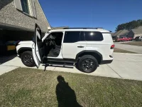
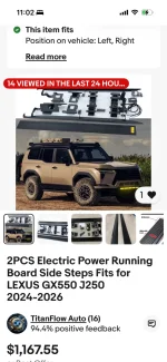
I took the plunge on the power step with the front strip light for my '25 OT+ on eBay from seller Vroomify in China.
2PCS Deployable Electric Running Board Side Steps Fit for LEXUS GX550 2024-2025 | eBay
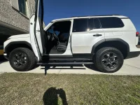
They look and work great, and I am pleased. The quality, fit and integration is very good. The instructions could be a lot better, but it can be deciphered.
Here a a few notes which may be helpful to those doing this project:
-Be sure to specify which GX550 model you have. There are differences depending on model. If you order, they also should ask for your VIN number.
-The parts list in the instructions is full of errors on the included hardware and quantities. Take it with a grain of salt.
- There are 3 'T-bolts' referenced in the instructions which are a bit confusing. These slip into oval openings that are not threaded to help hold the left rear and right rear brackets. Further complicating matters on my vehicle, was that the smaller left rear T-bolt needed its width trimmed a bit to fit in the chassis opening and there was no opening at all for the right rear T-bolt. I just left the right rear bolt out to avoid having to cut a hole in the chassis. There are still 2 other bolts holding this bracket.
-Locating the connector they use to tap the Canbus on the GX can be a little tricky. You need to remove the the plastic shell at the base of the steering wheel. It is best to extend the steering wheel out and down. Then there are two philips screws on top and one below that need to be removed to allow the shell halves to snap apart. I have included a photo of the connector location.
-(Optional) If you want to avoid using fuse taps in the fusebox which do not allow the interior (right passenger footwell) fusebox cover to shut, you can pick up
the same circuit from a different connector under the the steering wheel using a BLUE posi-tap (
Posi-Tap PTA1618 Re-usable BLUE WIRE TAP (EX-150B, #605) 14-16 Awg, 5 PACK New! | eBay) on the white wire, (pin 2) of the connector I show in the additional photo. You will need to splice in your own 25 amp inline fuse to do this.
-The bracket to chassis bolts should be slightly loose before fitting the steps. Position and tighten the hex bolts on the steps to get the right alignment before tightening down the chassis brackets.
-As suggested earlier in this thread, tighten the gap filler panels right up to the body without spacers. This should get the alignment pretty close before you start adding spacers to the pedal brackets to tweak positioning as needed. You should adjust for nearly silent operation with no interference on retraction.
- I second the recommendation in this thread to mount the controller on the right side of the passenger footwell fusebox.
-Running wires between footwells is easiest if the padded panels under the dash are removed on each side of the center console in the footwells. They just pull out.
-The app seems to have trouble connecting sometimes. It seems to resolve when reinstalled. Fortunately, you really do not need to access the app very often, (just for lighting setup or if you want to turn off the steps).
Canbus tap location under steering wheel.
Alternate power tap (white wire, pin 2) under steering wheel (suggestion, not required)